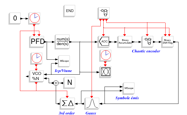
Chaotic frequency hopping emitter
nb_coef = 33+28

lines(-1);

F_cpf   = 20e6;
T_cpf   = 1/F_cpf;
sig_ref = T_cpf*0.02/100

Fo = 2.045e9;
To = 1 / Fo;
wo = 2*%pi * Fo;
kv = 100.5e6;

alpha = 6.91e9;
beta2 = 0.15;
j_vco = 0.2e6;

Fd = 2.5e9;
N  = int(Fd/F_cpf)

Nsampl = 2;
Tsampl = 1/(F_cpf*Nsampl);
Fsampl = 1 / Tsampl;

Icp   = 5e-3;
Ileak = 0.1e-6;
fn    = F_cpf/180;
phi   = %pi/4;

Ts   = 3/fn
Nech = 12
Te   = Ts/Nech

M    = 32
Nbit = 3
a    = 0.5
b    = -1

[tau1,tau,tau2]=calcul_3eme_ordre(fn,phi,kv*2*%pi,Icp,N);
s    = poly(0,'s');
num  = 1+tau1*s;
den  = tau*s*(1+tau2*s);

Tfin = 1000e3*T_cpf
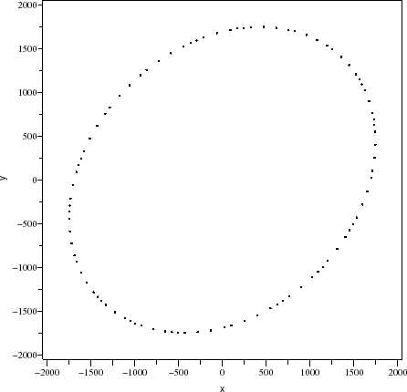
Figure : Phase plan of chaotic encoder
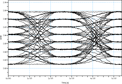
Figure : Eye diagram of the input voltage of the VCO
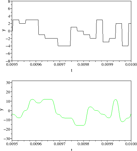
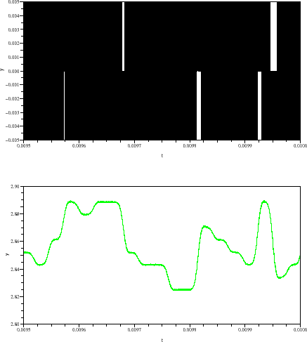
Figure : (a)Output of chaotic encoder;(b)Filtered signal at the input of the modulater Delta-Sigma
Figure : (a) Output current of the PFD;(b) Tunning voltage of the VCO
A. Layec
