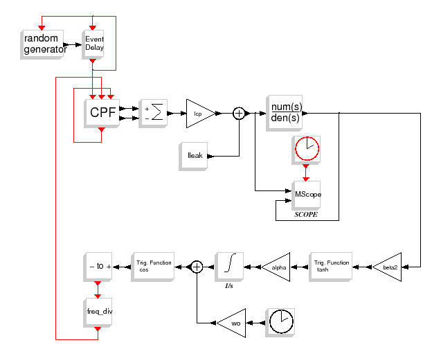

This diagram realizes the simulation of a Type-2 integer ![]() frequency synthesizer with the continuous time behavior of the Scicos
simulator.
frequency synthesizer with the continuous time behavior of the Scicos
simulator.
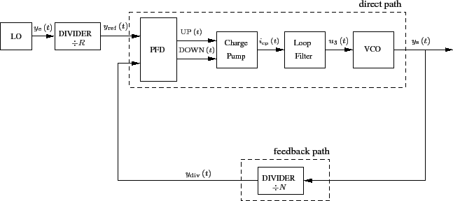
A general block diagram of such a subsystem can be illustrated by the
following figure.

Type-2 ![]() frequency synthesizer is composed of :
frequency synthesizer is composed of :
When it is understand in linear domain, this subsystem doesn't really differs from a classical Phase Locked
Loop[1] (PLL).
It only adds a frequency divider ![]() in a feedback path to
convert the high frequency coming from the VCO.
in a feedback path to
convert the high frequency coming from the VCO.
With this feedback divider, the output frequency of the synthesizer is
given by :
![]()
//**PFD**//
F_ref = 50e6;
T_ref = 1/F_ref;
//Noise variance of LO
sig_ref=T_ref*0.1/100

//**VCO**//
Fo = 2.045e9;
To = 1 / Fo;
wo=2*%pi * Fo;
kv = 100.5e6; //local sensitivity
//coef for input nonlinear caracteristic
alpha=6.91e9;
beta2=0.15;
//white noise power
j_vco=1e6;

//**feedback divider**//
N=52;

//**output frequency**//
Fd=N*F_ref;

//**sampling clock of VCO**//
Nsampl = 4;
Tsampl = 1/(Fd*Nsampl);
Fsampl = 1 / Tsampl;

//**charge pump**//
Icp = 5e-3;
Ileak=10e-6;

//**loop filter**//
fn=F_ref/180;
phi=%pi/4;
kv=kv*2*%pi
[tau1,tau,tau2]=calcul_3eme_ordre(fn,phi,kv,Icp,N);
s=poly(0,'s');
num=1+tau1*s;
den=tau*s*(1+tau2*s);
kv=kv/(2*%pi)

//**final time simulation**//
Tfin=1000*T_ref
