Second order Infinite Impulse Response filter
The Fig. 1 presents the block diagram of an ideal second order digital filter.
Figure 1: Block diagram of a linear second order digital recursive filter
The differential discrete equation that described the system is given by:
This linear system is traditionally studed by the following Z function transfert :
With this previous equation, we can find the stability domain of the filter according to the gain paramaters  and
and  .
So the Fig.2 represents the stability domain of the second order recursive filter.
Figure 2: Stability domain of the second order recursive filter
By changing the ideal operators (adders and multipliers) by real operators that are presents in Digital Signal Processors (DSP), we can associate a nonlinear function for each operators.
It is the modulo function which represents the effect of the overflow that occurs in digital implementation.
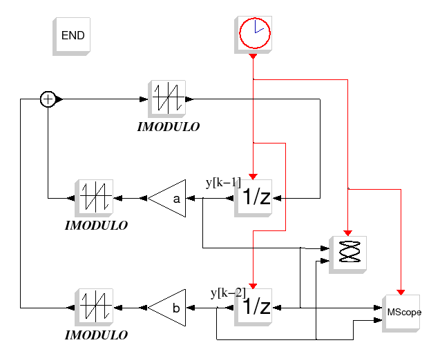
The system is then described by the following nonlinear discrete state system :
which is the simulated system in this scicos diagram.
Te     = 1
Nbit   = 31
a      = 0.5
b      = -1
ci     = 0.675
Intmax = 2^(Nbit-1);
ci1    = -int(ci*Intmax)
ci2    = int(ci*Intmax)
Tfin   = 1e4*Te
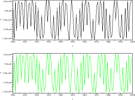
Figure : (a) Time domain waveforms of discrete state variables
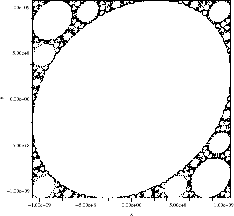
Figure : (b) Phase plan
A. Layec
- [1]
L. O. Chua and T. Lin, ``Chaos in digital filters,'' IEEE Trans.
Circuits Syst., vol. 35, no. 6, pp. 648-658, Juin 1988.
- [2]
T. Lin and L. O. Chua, ``On chaos of digital filters in the real world,''
IEEE Trans. Circuits Syst., vol. 38, no. 5, pp. 557-558, Mai 1991.


![]()
![]()

