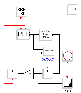
Locked synthesizer diagram
//## LO
F_cpf   = 20e6;
T_cpf   = 1/F_cpf;
sig_ref = 2*%pi

//## VCO
kv    = 133e6;
alpha = 6.91e9;
beta2 = 0.15;
j_vco = 30e3;

//## DIVIDER
Fd = 2.50e9;
N  = int(Fd/F_cpf)

//## CHARGE PUMP
Icp       = 5e-3
Ileak     = 8e-6
Ileak_sig = 0e-6

//## LOOP FILTER
fn  = F_cpf/290
phi = %pi/4
kvv = kv*2*%pi
[tau1,tau,tau2] = calcul_3eme_ordre(fn,phi,kvv,Icp,N);

//## custom components
C1=820e-12;
C2=150e-12;
R1=1500;
Rvco=5e+3;
Cvco=25e-12;
//tau1=C2*R1;
//tau=C2+C1;
//tau2=R1*C1*C2/(C2+C1);
//tauvco=Rvco*Cvco

s   = poly(0,'s');
num = 1+tau1*s;
den = tau*s*(1+tau2*s);

//## LINEAR MODEL
G  = kvv*Icp/(2*%pi)*num/(s*den);
H  = num/den
GH = kvv*Icp/(2*%pi)*num/(N*s*den)

//## cont_frm
f11=cont_frm(num,den);
s11=syslin('c',f11.A,f11.B,f11.C);

//## tf2ss
f22=tf2ss(num/den,%eps)
s22=syslin('c',f22.A,f22.B,f22.C);

//## SPECTRUM ANALYSIS
Tsampl = 1/100e6
nfft   = 2^16
aver   = 8

//## SIMULATION EVENTS
Tacqui = 5e-5+0.025e-3
Tfin   = Tacqui + aver*nfft*Tsampl
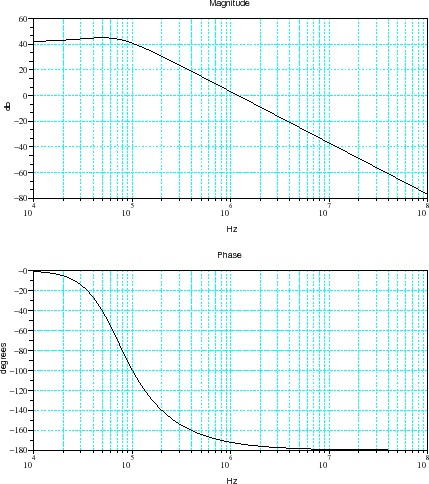
Figure : Closed-loop transfert function
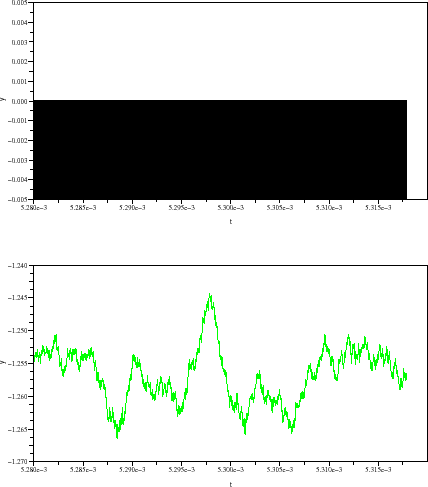
Figure : Time domain wave forms.(a) Output current of the PFD;(b) Tunning voltage of the VCO
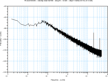
Figure : Output power spectral density
A. Layec


