Continuous Voltage Controlled Oscillator
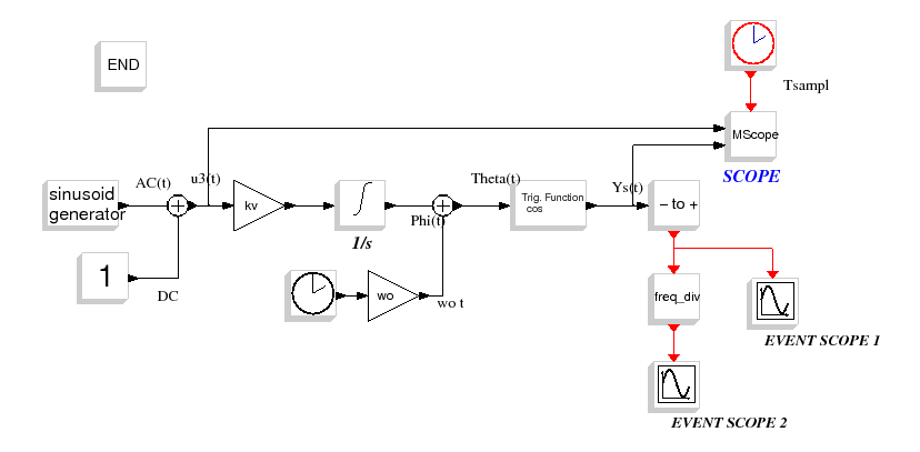
This diagram realizes an open loop model of a continuous Voltage Controlled Oscillator.
Regular output of the VCO is described with the following formula :
with
 the free pulsation of the VCO,
 the linear sensitivity
(expressed in rad/s) and
  the control voltage.
Integration of input voltage and detection of crossing are made with the
integral block and zeros crossing block of scicos which use the integrated solvers lsoda or
daskr.
Fo     = 10e6
To     = 1/Fo
wo     = 2*%pi*Fo
alpha  = 60e6
kv     = 60e6
j_vco  = 100e6
N      = 3
Nsampl = 80
Tsampl = To/Nsampl
Fsampl = 1/Tsampl
Tfin   = 15*To
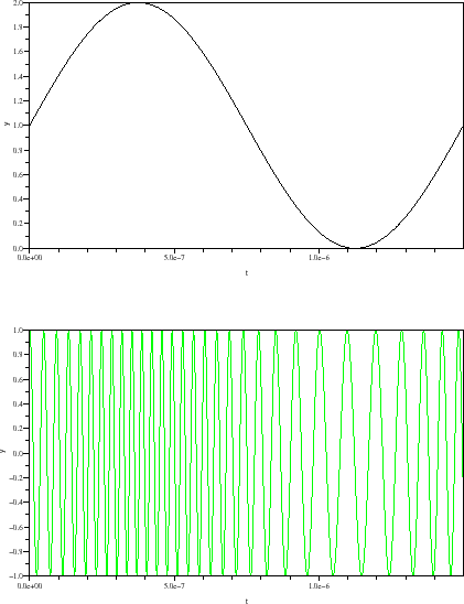
Figure : Input and output voltage of VCO
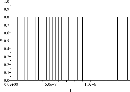
Figure : Events generated by the - to + block
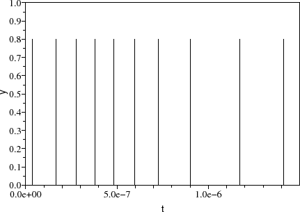
Figure : Events generated by the frequency divider block
A. Layec


![\begin{eqnarray}
y_{\rm {s}}\left(t\right)=\cos \left[\left(\omega_{0}t\right)+\int^{t}_{0} k_{\rm {v}} u_{3}\left(\tau\right)d\tau\right],
\end{eqnarray}](../../images/scicos_vco_diagr_img2_eng.gif)


