Discrete Voltage Controlled Oscillator
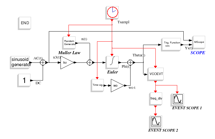
This diagram is an open loop model of a discrete Voltage Controlled Oscillator.
The regular output voltage can be described with this continuous equation :
The noise added in the the tunning voltage is a White Gaussian Noise.
The time domain integration of the input voltage is realized with the "EULERINTEGRAL"
block that uses a discrete backward-Euler rule and
the "VCOEVT"
block produces events corresponding to zero crossings of the output waveform with a discrete method of detection.
Fo     = 10e6
To     = 1/Fo
wo     = 2*%pi*Fo
alpha  = 60e6
kv     = 60e6
j_vco  = 100e6
N      = 3
Nsampl = 80
Tsampl = To/Nsampl
Fsampl = 1/Tsampl
Tfin   = 15*To
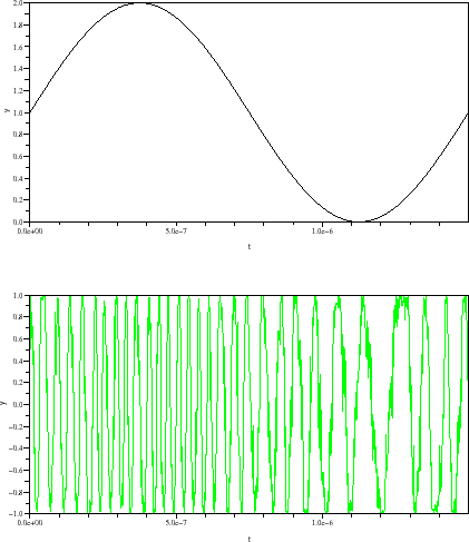
Figure : Input and output voltage of VCO
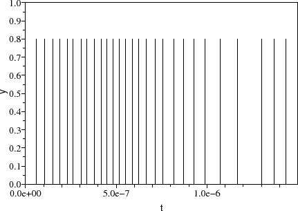
Figure : Events generated by the VCOEVT block
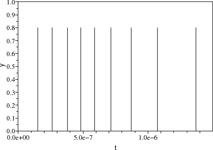
Figure : Events generated by the frequency divider block
A. Layec


![\begin{eqnarray}
y_{s}\left(t\right)=\cos \left[\left(\omega_{0}t\right)+\int^{t}_{0} k_{v} u_{3}\left(\tau\right)+n(\tau)d\tau\right]
\end{eqnarray}](../../images/discr_vco_diagr_img2_eng.gif)


